Direct Answer: Verify stainless steel equipment through a traceable chain from purchase specification to delivered machine. Define the material designation and applicable standard, nominal thickness and tolerance, surface finish, weld and joint acceptance, cleaning or passivation requirements, material certificate type, positive material identification scope, and incoming-inspection method before fabrication. At receipt, match documents, markings, components, measurements, and serial identity; record deviations instead of relying on appearance or magnet response.
This is a quality-verification workflow. It does not decide whether 304 or 316 is the correct alloy for a corrosion environment, and it does not establish food-contact legality for every destination. Those questions must already be resolved in the approved design basis. The inspection plan asks a narrower question: did the supplier deliver the material, dimensions, finish, fabrication condition, treatment, and records that the contract requires?
Start with a controlled specification and a material map. Use HSYL’s materials and fabrication guides to coordinate drawing callouts, then connect document and witness points to the FAT and compliance guides. If a requirement is absent from the contract, an inspector should not invent it at the loading dock.
1. Convert “Stainless Steel Construction” into Verifiable Requirements
A purchase description should identify which component uses which material. Separate food-contact surfaces, splash zones, tanks, frames, skins, backs, undersides, fasteners, shafts, guards, and purchased assemblies. State the material designation system and governing product standard, because similar shorthand can refer to different national designations or product forms. Standards must be checked for applicability to the product, edition, and destination.
ASTM’s current A240/A240M specification, for example, covers stainless plate, sheet, and strip for defined applications and includes chemical and mechanical requirements. Citing it does not automatically make it the correct standard for every bar, tube, casting, pressure part, or finished machine. The procurement record should identify the relevant standard for each product form rather than attaching one familiar number to all components.
| Specification field | What to state | Verification route |
|---|---|---|
| Component identity | Drawing item, zone, part number, revision | Drawing and bill-of-material match |
| Material | Grade or designation, product form, applicable standard and edition | Certificate, marking, traceability, agreed PMI |
| Thickness or section | Nominal value, permitted tolerance, measurement locations | Calibrated dimensional inspection |
| Finish | Process or reference sample, direction, protected faces, acceptance criteria | Visual comparison and specified instrument check |
| Fabrication | Joint detail, weld finish, distortion, sharp-edge and crevice criteria | Visual, dimensional, and specified NDT |
| Surface treatment | Cleaning, descaling, pickling or passivation procedure and acceptance | Process record plus agreed verification test |
2. Verify Material Certificates and Traceability Before Testing
A certificate is useful only when it can be linked to the delivered material. Check issuer, purchase order, material designation, product form, heat or lot number, dimensions, applicable standard, results, declaration, date, and authorized validation. Then follow the heat or lot identity through stock control, cutting, forming, subcontract work, assembly, and finished-equipment records.
Define the certificate type in the purchase order instead of asking for an unspecified “material certificate” after fabrication. The buyer should state whether a manufacturer-issued inspection document, independent witness, laboratory report, or another record is required under the contract. If original markings are removed during cutting, the fabricator needs an approved transfer method. Photographs of loose certificates without a traceability chain do not prove which sheet entered the machine.
| Certificate check | Accept when | Hold when |
|---|---|---|
| Standard and designation | They match the approved specification and product form. | The designation is ambiguous, substituted, or outside scope. |
| Heat or lot | The identifier links to receiving and fabrication records. | No link exists between document and installed part. |
| Dimensions | Certificate and stock record match the ordered form. | Thickness or form is omitted or inconsistent. |
| Results | Required chemical and mechanical entries meet the cited standard. | Only a sales description or unverified transcription is supplied. |
| Revision control | Latest approved document is linked to the equipment record. | Multiple conflicting versions remain unresolved. |
3. Use Positive Material Identification as a Controlled Check
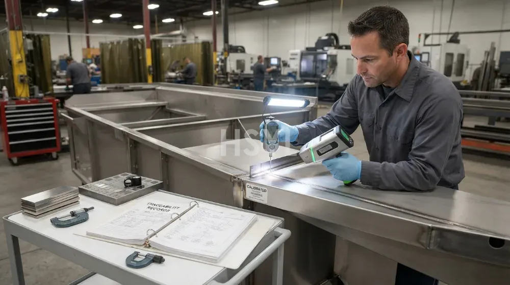
Positive material identification can supplement traceability or investigate a discrepancy, but the method and limitations must be defined. A handheld X-ray fluorescence analyzer can identify many alloying elements and help screen installed parts; it does not measure every element equally and may not resolve distinctions that depend on elements outside the instrument’s reliable capability. The operator needs calibration or verification checks, suitable reference materials, surface preparation, radiation controls, and documented measurement locations.
Specify whether PMI is required for every critical component or a risk-based sample. Record instrument identity, method, operator, reference check, result, acceptance basis, and exact tested location. Treat unexpected results as a hold point. Do not “average out” a wrong component, and do not use magnetism or an unqualified chemical spot test as a substitute for traceable identification. The material map should also prevent an enclosure-panel result from being presented as evidence for a food-contact tank.
4. Measure Sheet Thickness Against the Drawing and Tolerance
Thickness verification starts with the nominal callout and permitted tolerance agreed in the drawing or purchase specification. There is no universal thickness that proves commercial quality. Required thickness depends on component geometry, load, span, forming, pressure or vacuum where applicable, reinforcement, fabrication method, service, and the relevant design rules. This page therefore does not assign invented thickness values to equipment categories.
Use a calibrated micrometer or other suitable contact method at accessible edges when practical. Ultrasonic measurement may be useful where only one side is accessible, but coating, curvature, surface condition, coupling, material velocity, and operator technique can affect results. Agree the method, calibration blocks, locations, number of readings, treatment of coatings, and rounding rule. Measure formed areas and flat panels as separately defined populations rather than taking one convenient reading near an edge.
5. Define Surface Finish by More Than a Finish Name
Terms such as brushed, satin, mirror, or No. 4 can be interpreted differently across suppliers unless the governing standard, abrasive sequence or process, grain direction, roughness requirement where applicable, and approved reference sample are stated. Visual appearance and measured roughness are related but not interchangeable. A small roughness result does not reveal embedded iron, deep directional scratches, folds, pits, weld undercut, or residue.
Inspect under consistent lighting after protective film removal in the agreed inspection area. Record grain direction, color variation, scratches, dents, pits, embedded contamination, polishing transitions, edge condition, and cleanliness. If profilometry is required, define the instrument, cutoff, evaluation length, measurement direction, locations, and acceptance rule. Do not copy a universal roughness threshold from a different product standard or market.
| Surface feature | Inspection method | Acceptance basis | Typical record |
|---|---|---|---|
| Grain and appearance | Controlled visual comparison | Approved sample and drawing direction | Location photographs |
| Roughness where specified | Calibrated profilometer | Contract value and stated method | Instrument, settings, readings |
| Contamination | Visual plus agreed free-iron or cleanliness check | Specified treatment and test criterion | Test lot and result |
| Protective film damage | Removal and inspection at defined stage | No hidden damage beyond agreed limits | Pre-pack and receiving photos |
6. Inspect Welds, Joints, and Fabrication Condition
Define weld acceptance by joint function. Product-contact joints may need continuity, cleanable transitions, controlled contour, and removal of defects or residues. Structural joints may follow different visual or nondestructive-testing requirements. Specify permissible undercut, porosity, cracks, incomplete fusion indicators, sharp edges, spatter, burn-through, distortion, inaccessible gaps, and polishing condition through the applicable code or project criteria; do not use an undefined instruction to “polish all welds.”
Inspect both the visible bead and the surrounding heat-affected area. Confirm filler and procedure records where required, joint preparation, shielding and purge controls where applicable, post-weld finishing, and removal of carbon-steel contamination. Dye penetrant or other NDT should be used only with a qualified procedure, compatible materials, suitable cleaning, and acceptance criteria. For equipment families with repeated wet cleaning, review joint access in the dishwashing equipment category and product-contact interfaces in food-preparation equipment.
7. Specify Cleaning, Pickling, and Passivation Precisely
Cleaning, descaling, pickling, and passivation are related but not interchangeable. ASTM A380/A380M covers recommendations and precautions for removing contaminants that can impair corrosion resistance or sanitary condition. ASTM A967/A967M covers several chemical passivation treatments and alternative tests for effectiveness, while stating that it does not recommend a grade, treatment, or acceptance criterion for every application. The purchaser and supplier must agree which procedure and test apply.
The process record should identify the treated parts, precleaning, solution or method, concentration controls, temperature, contact time, rinsing, neutralization where applicable, water quality, drying, protection from recontamination, lot, operator, and acceptance result. Chemical work requires appropriate safety and environmental controls. A verbal statement that welds were “passivated” is not equivalent to a procedure and lot record.
8. Run a Documented FAT and Incoming Acceptance
At FAT, match the approved drawing, material map, certificate register, heat or lot traceability, PMI plan, thickness readings, finish records, weld inspection, surface-treatment records, labels, and serial identity. List every exception with disposition and approval owner. The FAT does not replace incoming inspection because transport damage, substituted loose parts, moisture, packaging residue, or lost documents may appear at receipt.
At destination, check package identity, equipment serial number, document revision, visible damage, protective film condition, corrosion staining, loose component identity, and the agreed sampling points before installation alters the evidence. Quarantine discrepancies and preserve photographs and measurements. Coordinate the destination review through HSYL’s service and support page and send the approved inspection plan through the technical enquiry page. Final standards applicability and acceptance remain project-specific.