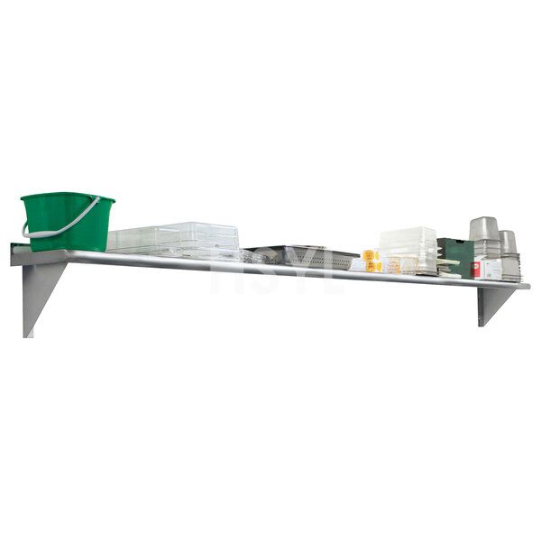
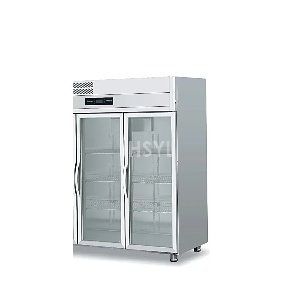
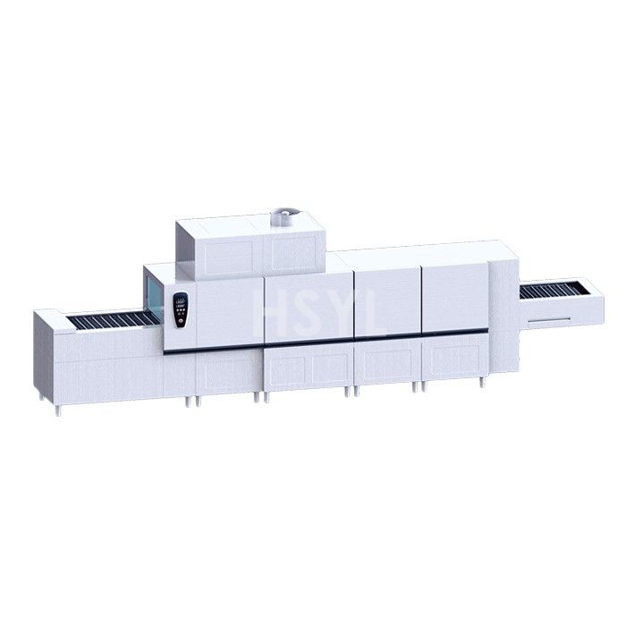
A shop drawing is not approved because its overall length matches the schedule. A fabricated sink, bench, hood surround, shelving unit or equipment plinth becomes part of several systems at once: food workflow, cleaning, structure, utilities, adjoining equipment, finishes, delivery and maintenance. Review it by interface and release it only when the evidence agrees.
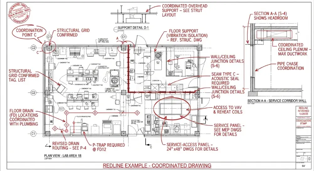
Hold Point 1 — Freeze the reference information
Identify drawing number and revision, equipment item, approved schedule entry, room/axis, current architectural and services backgrounds, site survey date and all referenced cut sheets. Mark discrepancies instead of choosing the most convenient dimension.
Use verified site dimensions where construction tolerances or existing conditions matter. Show whether dimensions are finished, structural or nominal and where adjustment is permitted. A fabrication allowance should be a deliberate detail, not an undocumented gap filled on site.
Hold Point 2 — Read plan, elevation and section together
Trace overall size, working height, top thickness/build-up, upstands, downturns, legs or plinth, bracing, undershelves, wall fixing and floor relationship across every view. Confirm edges and corners appropriate to the task and cleaning method. Locate seams where they do not create an unresolved hygiene, strength or appearance problem.
Show adjoining walls, columns and equipment. Test door, drawer, panel, filter, basket and trolley movements at full travel. Add operating and maintenance access envelopes; physical fit at installation is not proof that a component can later be removed.
Hold Point 3 — Coordinate every penetration and service
Dimension sinks, bowls, waste outlets, taps, splashbacks, cable or pipe penetrations, equipment cut-outs and builder’s work openings from stable references. Add outlet elevations and the route to receptors where drainage is involved. Confirm who supplies each valve, fitting, flexible connection, trap, isolator and seal.
The U.S. federal guide specification UFGS 11 05 40 calls for foodservice detail drawings to show items such as adjacent construction, utility schematics, drain lines, floor drains and maintenance access. It is a useful coordination example, not the project’s automatic governing specification.
Hold Point 4 — Make material and construction statements traceable
Identify material by component, not with a single note floating over the sheet. Record the specified grade only where project evidence supports it, plus finish, thickness or structural basis, joining/finishing method, reinforcing, backing and treatment of dissimilar-material contact where relevant. Do not assume every hidden bracket or underside shares the visible top’s material.
Use the 304 vs 316 stainless-steel guide to frame environment and component decisions, then use the stainless-steel verification guide to define documentary and test evidence. The shop drawing must point to the approved requirement; appearance alone does not verify grade.
Hold Point 5 — Simulate delivery, assembly and replacement
Check maximum shipping piece, weight and lifting points where required, doorway and lift limits, corridor turns, final assembly method, protective finish, site welding/polishing restrictions and storage before installation. Identify removable sections and field joints. Confirm that floors and walls can receive the intended anchorage.
Now simulate replacement of the least accessible component. If another trade or fabricated panel must be removed, document the sequence and responsibility. Add serial/item identification and as-built information needed for future parts or remanufacture.
Release by status, not by email silence
Use explicit outcomes: approved, approved with incorporated comments, revise and resubmit, or held for named information. Maintain a comment register with owner and closure evidence. Changes after release require a controlled revision and an assessment of material already fabricated.
Before sending a custom request through the commercial stainless-steel equipment category or HSYL project inquiry, include the interface drawing, site evidence, material requirement and approval path. A detailed RFQ reduces assumptions; it does not remove the need for coordinated shop-drawing review.