A commercial kitchen equipment utility schedule fails when it becomes a late transcription of catalogue data. Its real purpose is to control the handoff between the selected equipment, the building services and the people responsible for each final connection. Every row should tell the project team what is known, what is still provisional, where the interface occurs and which revision is allowed to drive construction.
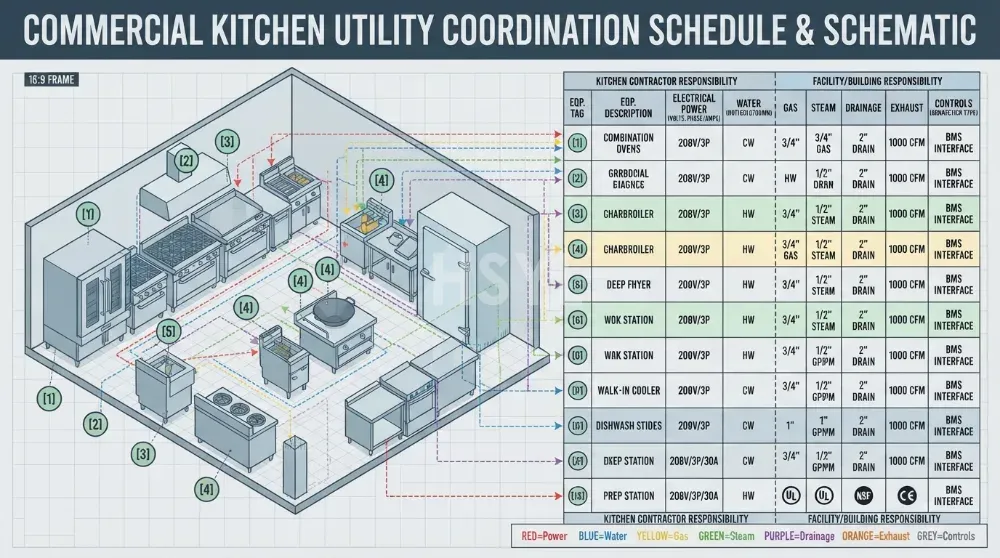
Give Every Equipment Item One Stable Identity
Start with the equipment tag, not the utility value. The same tag should appear on the kitchen plan, equipment schedule, builder's-work drawings, MEP drawings, supplier submittals, cable and pipe references, FAT records, installation checks and punch list. If one drawing calls an appliance K-27 while another calls it OVEN-3, the team can coordinate the wrong connection even when both documents contain technically correct data.
The U.S. Department of Defense guide specification UFGS 11 06 40.13, Foodservice Equipment Schedule, is project-specific rather than a universal kitchen standard, but it illustrates a useful control principle: equipment on plans and schedules is identified consistently, while dimensions and applicable electrical, gas, water and drain requirements are coordinated with other work. Adopt that traceability principle, then use the fields, codes and approval process required by the actual destination and project contract.
| Identity field | What it controls | Common failure |
|---|---|---|
| Equipment tag | Connection between plans, schedules, submittals and tests | A temporary design tag is replaced on one document but not the others |
| Location and room | Which services and isolation points belong to the item | The model moves during layout development but its utility point does not |
| Model status | Generic, basis-of-design, proposed, approved or as-built condition | A candidate model is treated as an approved purchase |
| Configuration suffix | Energy source, handedness, options and accessories affecting interfaces | The correct base model is scheduled with the wrong voltage or drain option |
| Source revision | Which data sheet or drawing supports the row | Values remain after the supplier drawing has changed |
Separate Supplier Data from the Engineer's Design Decisions
One number should not carry four different meanings. A nameplate input describes the selected equipment configuration. A connected load records what is physically connected. A design demand is established by the responsible engineer after considering operating modes, simultaneous use, starting conditions and the rules accepted for that project. The final connection size or protection is another project decision. Mixing these values in one column creates hidden assumptions.
Use separate fields for supplier-required conditions and building-design outputs. For electrical coordination, the existing electrical standards and power configuration guide explains why voltage, phase, frequency, rated input, operating mode and demand are not interchangeable. The utility schedule should link to that discipline's calculation; it should not replace it.
| Layer | Typical owner | What belongs here | What must not be inferred |
|---|---|---|---|
| Equipment requirement | Manufacturer or approved supplier | Rated supply, inlet condition, permissible range, connection type and operating mode for the selected configuration | Building capacity or final branch design |
| Project operating basis | Operator and kitchen planner | Which loads operate together, production windows, standby modes and resilience scenario | A universal diversity factor |
| Engineering design | Responsible MEP and fire engineers | Demand, distribution, protection, pipe or duct design and system controls | Automatic acceptance of catalogue values as final design |
| Field connection | Installing contractor with supplier review | Point, size, orientation, isolation, access, mating part and tested as-built condition | Permission to relocate the equipment interface without approval |
Build the Schedule Around Interfaces, Not Discipline Silos
A kitchen appliance may require electricity, potable water, treated water, hot water, gas, steam, condensate, indirect waste, direct waste, exhaust, make-up air coordination, data and remote interlocks. Only include utilities that actually apply, but use enough detail for each responsible discipline to make and check its decision. Blank should mean “not yet confirmed” or “not applicable” through an explicit status—not an invitation to guess.
| Interface family | Supplier information to request | Project coordination questions |
|---|---|---|
| Electrical | Supply characteristics, rated input/current, operating modes, connection type, protective and control requirements | Distribution capacity, isolation, protection, cable route, shutdown logic and local compliance |
| Water | Quality range, inlet pressure/temperature range, peak and operating consumption where documented, connection and treatment needs | Available condition, backflow protection, treatment ownership, isolation, flushing and test point |
| Gas | Approved gas family, inlet condition, rated consumption, connection and combustion/ventilation requirements | Local gas design, pressure regulation, isolation, detection, interlocks, commissioning and authority approval |
| Steam and condensate | Steam condition, demand basis, connection, condensate duty and equipment restrictions | Generation capacity, pressure control, trapping, return or disposal, access and safe isolation |
| Drainage | Discharge type, location, expected temperature or intermittent flow where known, air-gap or indirect-waste requirement | Drain classification, receptor, route, capacity, grease management, falls, access and local code |
| Exhaust and heat rejection | Appliance duty, effluent characteristics, manufacturer clearances and any listed hood/interface conditions | Hood type and coverage, airflow, make-up air, room balance, fire system and commissioning method |
| Controls | Enable, alarm, communication and interlock points with defined signal behavior | Cause-and-effect, BMS responsibility, fire/gas shutdown, cable ownership and witnessed functional test |
Do not copy a utility value from a similar model or another project. Record the exact source, model and configuration. Where the model is not selected, state the performance or interface requirement and keep the connection data provisional. This is more useful than filling the row with a plausible value that later reaches construction.
Coordinate the Physical Connection, Not Only the Number
A correct load can still produce an unusable installation when the connection point is on the wrong side, behind a fixed panel, inside a cleaning zone or beyond the contractor's agreed scope. Record the connection coordinates or drawing reference, height, orientation, service clearance, flexible or rigid connection basis, isolation location and responsibility for the final mating component.
Check the delivery and maintenance state as well as the operating state. Can the equipment be moved into position without damaging a capped service? Can a technician reach the isolation point without crossing a hot line or dismantling unrelated equipment? Can the unit be pulled out for service while respecting flexible connection limits? Can the floor drain and cleaning method work without directing water toward an electrical point?
Ventilation is especially sensitive to spatial coordination. The ASHRAE kitchen ventilation chapter notes that appliance arrangement and hood coordination affect system performance and energy use. Use the project-specific commercial kitchen ventilation guide to develop the hood system. The utility schedule should carry the released appliance duty, position and interface status into that design rather than invent an exhaust value.
Use Status Codes That Prevent Provisional Data Becoming Construction Data
Every utility field needs a status and a source revision. A practical sequence may distinguish requirement, supplier-proposed, design-coordinated, approved for construction, installed and as-built values. The project may use different names, but it needs an unambiguous rule for who can advance each status.
- Requirement defined: the operating duty and necessary interface are known, but a final model may not be selected.
- Supplier data received: the candidate configuration and source document are identified.
- Discipline review completed: responsible engineers have checked capacity, route, protection and code implications.
- Coordinated for construction: layout, builder's work, services and equipment data refer to the same released revision.
- Installed and verified: the physical point, labels, isolation and connection match the approved information.
- As-built recorded: authorized changes and final test records are incorporated into handover documents.
Do not use color alone as the status system; it can disappear in printing and does not explain approval authority. Include a written code, date, responsible role and source. The project-document route can organize equipment schedules and interface registers, while model-controlled connection drawings should remain traceable to the selected equipment.
Resolve Conflicts Through an Interface Decision Record
Utility conflicts are normal during design development. The risk comes from resolving them informally. When the selected oven changes its connection position, a dishwasher requires different incoming water, or the hood lineup changes, open an interface decision record. State the affected tag, old and new source, disciplines impacted, construction consequence, decision owner and documents requiring revision.
Do not overwrite the schedule and leave conflicting drawings untouched. The equipment schedule, architectural penetrations, MEP layouts, control cause-and-effect, procurement data and installation method may all need coordinated reissue. If work has already been built, record the field condition and authorized disposition instead of silently changing the design value to match the mistake.
Verify the Schedule at Factory, Site and Handover Stages
At FAT, compare the witnessed equipment identity, nameplate, connection locations, loose mating parts, interface labels and supplier drawings with the approved schedule. Factory utilities may not reproduce the final site, so identify which functional checks remain for SAT. The commercial kitchen equipment FAT checklist provides the wider acceptance framework.
Before connection on site, reconcile the tag, model, configuration and approved source revision. Inspect point location, access, isolation, cleanliness, flushing where applicable and contractor responsibilities. During commissioning, verify operating modes and interlocks under the agreed safe method. At handover, issue the as-built schedule with open items clearly identified; a construction-stage spreadsheet with unresolved assumptions is not an operating record.
Issue a Utility Package That Can Be Reviewed Without Guessing
The deliverable should include the controlled utility schedule, tagged layout, model-specific connection drawings, discipline calculations and drawings, responsibility matrix, cause-and-effect where needed, decision log, approved deviations and commissioning records. Keep units visible and consistent. Protect formulas and status fields from accidental overwrite if a spreadsheet is used.
For a project-specific review, provide HSYL with the menu and duty, equipment schedule, current layout, destination market, available utilities and unresolved interfaces through the project enquiry route. HSYL can then return model-specific data and coordination questions for the proposed scope; the project's licensed or responsible engineers retain authority for the building-service design and local approval.