Direct Answer / Key Takeaway: Engineering guide to commercial kitchen hood sizing. Calculate CFM by cookline duty (light to extra-heavy), select UL 1046 baffle filters, and balance make-up air.
When engineering ventilation infrastructure within our Utilities & Ventilation Hub, Mechanical, Electrical, and Plumbing (MEP) engineers and commercial kitchen consultants confront a precision aerodynamic challenge: calculating commercial kitchen hood exhaust airflow (Cubic Feet per Minute / CFM) that guarantees 100% thermal plume capture while minimizing conditioned air energy penalties. Sizing an exhaust canopy too small causes grease aerosols, heat plumes, and carbon monoxide to spill into prep lines and dining spaces, precipitating severe health code violations and fire hazards under NFPA 96. Conversely, oversizing exhaust CFM inflates Make-Up Air (MUA) heating and cooling utility costs by thousands of dollars annually.
This technical engineering specification guide breaks down commercial kitchen hood sizing across cooking appliance thermal classifications (Light, Medium, Heavy, Extra-Heavy Duty), canopy physical geometry (wall-mounted, single island, double island), UL 1046 baffle grease filter selection, aerodynamic duct velocity thresholds (1,500 to 2,500 FPM), and the delicate static pressure balance required between exhaust volume and make-up air introduction.
Key takeaway: Commercial kitchen ventilation is a closed aerodynamic mass balance, not an isolated fan selection. Under International Mechanical Code (IMC Section 507) and ASHRAE 154, exhaust CFM must be calculated from the highest thermal duty appliance on the continuous cookline, plus an overhang allowance of at least 6 inches (150 mm) on all open sides. To prevent negative pressure chokes, make-up air must deliver 80% to 90% of exhaust volume directly into the kitchen space, leaving a controlled 10% to 15% negative pressure buffer to contain cooking odors.
1. Regulatory Standards and Hood Classification: Type 1 vs. Type 2
Commercial kitchen ventilation operates under a rigorous web of international mechanical codes and life-safety mandates: NFPA 96 (Standard for Ventilation Control and Fire Protection of Commercial Cooking Operations), International Mechanical Code (IMC Sections 506 and 507), and ASHRAE Standard 154. Central to compliance is classifying whether your cookline demands a Type 1 or Type 2 canopy.
Type 1 Hoods (Grease, Smoke & Fire Hazard Protection)
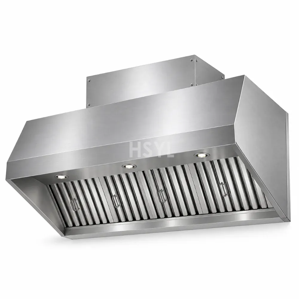
A Type 1 hood is legally mandated over any commercial cooking equipment that produces grease-laden vapors, smoke, or open flames during preparation. This encompasses commercial deep fryers, gas charbroilers, griddles, open gas ranges, tilting braising pans, and wok ranges. Engineering requirements for Type 1 canopies include:
- Liquid-Tight Continuous Welds: The canopy shell must be fabricated from minimum 1.2 mm (18-gauge) AISI 304 stainless steel or 1.5 mm (16-gauge) carbon steel, with all internal corner seams continuously TIG-welded liquid-tight to prevent liquefied grease from leaking into wall cavities.
- UL 1046 Certified Baffle Filters: Mesh filters are prohibited under NFPA 96. Canopies must feature interlocking stainless steel or aluminum baffle filters that act as a flame barrier, forcing air through centrifugal turns to separate grease droplets into an enclosed drainage channel.
- Pre-Engineered Wet Chemical Fire Suppression: Type 1 hoods must incorporate integrated fire suppression piping (e.g., UL 300 compliant potassium acetate or alkaline solution networks) targeting cooking surfaces, grease filter banks, and exhaust duct collars with thermal link activation.
Type 2 Hoods (Condensate, Heat & Odor Removal)
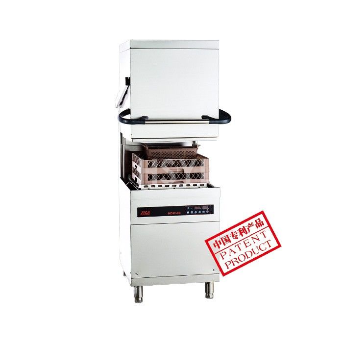
A Type 2 hood—frequently designated as a condensate or steam hood—is engineered exclusively for non-grease thermal equipment that generates excessive heat, moisture, or steam plumes. Typical applications include flight-type and conveyor dishwashers (see our Commercial Dishwasher Sizing Guide), steam-jacketed kettles (see our Steam-Jacketed Kettle Sizing Guide), pasta boilers, and commercial deck ovens.
Type 2 hoods do not require grease filters or automated fire suppression systems. Instead, they incorporate internal perimeter condensate gutters sloped to a drain tap, preventing condensed steam from dripping back onto sanitized dishware or baked food items.
2. Cookline Thermal Duty Classifications & Exhaust CFM Benchmark Matrix
Thermal plumes generated by commercial cooking appliances behave according to convective buoyancy. Plumes from electric holding cabinets rise slowly with low convective velocity, whereas radiant charbroilers and wok burners generate ferocious thermal updrafts exceeding 3.5 ft/sec (1.1 m/s) saturated with vaporized grease. IMC Section 507 and ASHRAE 154 divide cooking appliances into four thermal duty tiers.
| Appliance Thermal Duty | Representative Equipment Examples | Operating Temperature Range | Wall Canopy CFM / Linear Foot | Single Island CFM / Linear Foot | Double Island CFM / Linear Foot |
|---|---|---|---|---|---|
| Light Duty | Convection ovens, steamers, proofers, electric pasta cookers, holding carts | ≤ 400°F (204°C) | 150 – 200 CFM/ft | 250 – 300 CFM/ft | 200 – 250 CFM/ft |
| Medium Duty | Rotisseries, open-burner ranges, griddles, electric fryers, combi ovens | ≤ 400°F (204°C) | 200 – 300 CFM/ft | 300 – 400 CFM/ft | 250 – 350 CFM/ft |
| Heavy Duty | Gas deep fryers, gas charbroilers, radiant broilers, electric salamanders | ≤ 600°F (316°C) | 300 – 400 CFM/ft | 400 – 500 CFM/ft | 350 – 450 CFM/ft |
| Extra-Heavy Duty | Solid fuel appliances (wood, charcoal, briquettes), wok ranges, open lava stone broilers | > 600°F (316°C) | 400 – 550+ CFM/ft | 550 – 700+ CFM/ft | 500 – 600+ CFM/ft |
Governing Rule for Mixed Cooklines: When multiple appliances sharing different thermal duties are arranged under a single continuous canopy hood, the entire hood length must be sized based on the highest duty appliance present on that line, unless physical stainless steel side baffles isolate lower-duty zones.
3. Engineering Mathematics: Exhaust CFM Calculation Formulas
MEP design engineers employ two primary calculation methodologies: the Linear Foot Method (standardized in IMC building codes) and the Area Velocity Capture Method (utilized for high-plume or custom architectural geometries).
Method A: Linear Foot Exhaust Calculation (IMC Method)
The total required exhaust volume is calculated by multiplying the active hood length by the code-specified CFM coefficient according to canopy mounting configuration:
Q_exhaust = L_hood × CFM_factor
Where:
- Q_exhaust = Total exhaust volume in Cubic Feet per Minute (CFM)
- L_hood = Total length of hood canopy in feet (Equipment line length + end overhang allowances)
- CFM_factor = Code volumetric factor based on thermal duty tier and canopy style (from Matrix above)
Worked Example: Consider a 16-foot cookline featuring two gas fryers (Heavy Duty), one 6-burner gas range (Medium Duty), and a gas griddle (Medium Duty). The hood is wall-mounted, extending 6 inches past each end, yielding a total canopy length of 17 feet. Because gas fryers represent Heavy Duty, the minimum code coefficient is 350 CFM/linear foot:
Q_exhaust = 17 ft × 350 CFM/ft = 5,950 CFM
Method B: Area Velocity Capture Method (ASHRAE Capture Formula)
For custom island canopies or deep European cooking suites, capture velocity across the open face of the hood provides superior aerodynamic precision:
Q_exhaust = Area_hood × V_face
Where:
- Area_hood = Length (ft) × Width (ft) of the lower canopy opening
- V_face = Minimum face capture velocity across open area (typically 50 FPM for wall canopies, 75 to 100 FPM for exposed island hoods)
4. Canopy Physical Geometry: Overhangs, Mounting Heights & Side Panels
Even an industrial fan operating at maximum brake horsepower cannot capture cooking emissions if the physical hood envelope fails to intercept expanding thermal plumes. Hot air plumes expand outward at an angle of roughly 10 to 15 degrees from the cooking appliance surface.
- Minimum Side and Front Overhang: Under IMC Section 507.12, canopy hoods must overhang the cooking equipment perimeter by a minimum of 6 inches (150 mm) on all open sides. For high-plume charbroilers, wok ranges, or tall combi oven doors, engineering best practice requires extending front overhangs to 10 to 12 inches (250 mm to 300 mm).
- Mounting Height Above Finished Floor (AFF): The lower perimeter edge of a commercial exhaust canopy must sit between 78 inches and 84 inches (1,980 mm to 2,130 mm) AFF. Mounting lower than 78 inches causes chef head-strike hazards and obstructs sightlines; mounting higher than 84 inches allows cross-drafts to shear the thermal plume, requiring a 10% CFM increase for every additional 6 inches of elevation.
- The Impact of End Baffles / Side Panels: Installing full or partial stainless steel side panels (end skirts) between the hood edge and cooktop reduces cross-draft disruption and transforms an island airflow profile into a controlled wall canopy, slashing total required exhaust CFM by 15% to 25% without compromising capture efficiency.
5. Baffle Grease Filter Engineering & Duct Velocity Sizing
Grease extraction inside a Type 1 hood relies on mechanical centrifugal impingement within UL 1046 certified baffle filters. As exhaust air navigates interlocking vertical baffles, heavy grease droplets (greater than 8–10 microns in diameter) cannot execute high-speed directional turns, impinging onto metal surfaces and trickling into the grease trough.
UL 1046 Sizing & Filter Bank Velocity
Baffle filters must operate within a specific face velocity sweet spot between 250 and 400 FPM across the active filter face:
- Under-velocity (< 200 FPM): Air travels too slowly through the baffles; centrifugal force is insufficient to separate grease droplets, allowing airborne grease to enter exhaust ductwork.
- Over-velocity (> 450 FPM): High static pressure drop chokes exhaust airflow, causing whistling noise and pulling captured grease back out of the drainage troughs into the airstream.
- Mounting Pitch: Baffle filters must be installed at an angle of not less than 45 degrees from the horizontal to ensure gravity drainage of extracted oils into the perimeter grease collector.
Exhaust Duct Velocity Limits (NFPA 96 & IMC Section 506)
To prevent grease accumulation in horizontal duct runs while controlling fan noise and static pressure, duct cross-sectional area must maintain calibrated airflow velocity:
V_duct = Q_exhaust / Area_duct
Under NFPA 96, commercial exhaust ductwork must operate between 1,500 FPM and 2,500 FPM (with 1,800 FPM considered the industrial optimum):
- Velocities below 1,500 FPM allow aerosolized grease droplets to fall out of suspension and pool on duct floors, creating fuel for grease fires.
- Velocities above 2,500 FPM generate excessive aerodynamic rumble, elevate fan power consumption, and create high static pressure across fire dampers.
6. The Make-Up Air (MUA) Balance: Pressure Gradients & Delivery Methods
Exhausting 6,000 CFM from a kitchen removes 360,000 cubic feet of air every hour. If replacement air is not intentionally engineered, building air pressure drops, creating severe negative pressure that pulls odors backward, collapses ceiling tiles, and pulls carbon monoxide from gas water heater flues.
The 80% to 90% Balancing Rule
In high-efficiency commercial kitchen ventilation systems, dedicated Make-Up Air Units (MAU) supply 80% to 90% of the total exhaust volume. The remaining 10% to 20% deficit is drawn from adjacent dining rooms and corridors as transfer air. This maintains the kitchen at a slight negative pressure relative to the dining space (approximately -0.01 to -0.02 inches water column / -2.5 to -5.0 Pa), guaranteeing that cooking odors never escape into customer seating areas.
MUA Delivery Configurations Compared
| Make-Up Air Supply Strategy | Supply Air Speed | Aerodynamic Impact on Plume | Energy Efficiency & Comfort |
|---|---|---|---|
| Perforated Perimeter Plenum (PSP) | Low Velocity (100–150 FPM) | Negligible; air trickles gently downward outside hood face | High comfort; prevents plume shear; allows untempered air in mild climates |
| Front Face Discharge Plenum | Medium Velocity (250–350 FPM) | Moderate; discharges air across top perimeter | Direct capture assistance; requires tempered/heated supply air |
| Internal Short-Circuit Hood | High Velocity (> 500 FPM) | Severe risk; internal blasts cause turbulence and plume spill | Prohibited by many modern mechanical codes; low capture efficiency |
| Traditional Ceiling Diffusers | Variable (High throw) | High disruption if diffusers blow air directly toward hood edge | Must be located at least 10–12 feet away from hood face to prevent plume breakdown |
7. 5-Year Ventilation TCO & Demand-Controlled Ventilation (DCV) ROI
Treating kitchen ventilation solely as an upfront sheet metal expense ignores ongoing energy operating costs. Conditioning (heating in winter, cooling in summer) and moving 6,000 CFM of outside air 14 hours per day costs thousands of dollars each year. Below is a realistic 5-year operating cost analysis comparing a traditional constant-volume hood system against a Demand-Controlled Kitchen Ventilation (DCKV) smart system.
| 5-Year Ventilation Cost Category (14,000 Operating Hours) | Constant Volume System (6,000 CFM Continuous) | Smart DCKV System (Variable 3,000–6,000 CFM) |
|---|---|---|
| Exhaust & Supply Fan Electricity ($0.14/kWh) | $11,760 (7.5 kW continuous motor draw) | $5,290 (Affinity laws: 50% speed = 12.5% power) |
| Make-Up Air Heating Energy ($1.35/therm gas) | $18,900 (Conditioning outside winter air) | $9,450 (Reduced volume during idle/prep times) |
| Make-Up Air Summer Cooling ($0.14/kWh cooling) | $14,280 (Dehumidifying outside summer air) | $7,850 (Lower mass flow during low-fire periods) |
| Ductwork Cleaning & Maintenance | $4,500 (Quarterly professional scrape/degreasing) | $3,600 (Optimized filter capture reduces grease load) |
| Total 5-Year Operating Expenditure | $49,440 | $26,190 |
| 5-Year Operational Savings with DCKV | Baseline | $23,250 Net Utility Savings |
The Power of Fan Affinity Laws: Under aerodynamic fan affinity laws, fan power is proportional to the cube of airflow velocity: P2 / P1 = (CFM2 / CFM1)^3. Reducing hood exhaust speed by just 20% (to 80% airflow during idle prep periods) cuts fan electrical energy consumption by almost 50%.
Engineering Specification Checklist for MEP Contractors & Consultants
Before releasing fabrication drawings or submittal packages for commercial kitchen exhaust hoods, review the following engineering parameters:
- Verify Highest Thermal Duty: Audit all appliances under the canopy; size total CFM based on the most demanding equipment (e.g., solid-fuel grill or gas deep fryer).
- Confirm Physical Overhangs: Verify minimum 6-inch side and front overhangs (10–12 inches for charbroilers, wok ranges, and combi ovens).
- Audit UL 1046 Filter Angles: Ensure baffle filters are pitched at ≥ 45 degrees with an enclosed grease drain leading to a removable stainless collection cup.
- Verify MUA Supply Velocity: Avoid turbulent 4-way ceiling diffusers within 10 feet of the hood. Specify low-velocity perforated perimeter supply plenums (100–150 FPM).
- Ensure Static Pressure Match: Calculate system static pressure drop (hood + filters + ductwork + exhaust stack) and size the upblast centrifugal fan motor with a 15% static safety margin.
Discuss Your Kitchen Ventilation Design with HSYL Engineers
Share your cookline equipment schedule, kitchen floor plans, and ceiling heights with HSYL. Our project engineering team calculates precise exhaust CFM, designs custom Type 1 and Type 2 canopy configurations in AISI 304 stainless steel, and coordinates integrated make-up air plenums before fabrication begins. Contact HSYL for Commercial Kitchen Ventilation Engineering Support, or explore our full suite of utilities and ventilation engineering guides.