Direct Answer: Design commercial kitchen ventilation from the actual heat source and pollutant through hood capture, make-up air, pressure balance, fire protection and commissioning. There is no universal airflow rate; the responsible engineer must calculate the project values.
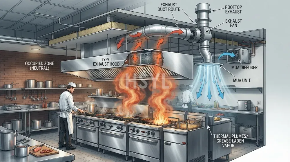
Begin with the contaminant and heat source
A cooking line does not emit one generic “kitchen load.” Each appliance produces a different combination of sensible heat, moisture, grease aerosol, smoke, combustion products and odor. The duty changes again with menu, loading, fuel, operating state and operator practice. Start with an appliance-by-appliance source schedule rather than a rule based only on hood length.
Record manufacturer data where available, but distinguish catalog data from the selected configuration. Identify the active cooking surface, plume location, opening direction, discharge event and adjacent disturbances. The source schedule should be shared with the kitchen planner, mechanical engineer and fire specialist before the hood is released for manufacture.
| Source behavior | Examples of relevant duty | Primary design concern | Evidence needed |
|---|---|---|---|
| Grease-laden plume | Frying, griddling, charbroiling or wok cooking as applicable | Capture, grease removal, duct access and fire protection | Appliance data, menu duty and authority classification |
| Moist plume | Boiling, steaming and warewashing discharge | Condensation, capture and room humidity | Operating cycle and discharge location |
| Combustion products | Fuel-fired equipment | Safe exhaust, replacement air and combustion stability | Fuel and flue arrangement from the selected model |
| Sensible heat | Hot equipment surfaces and open cooking | Worker exposure, plume buoyancy and cooling load | Manufacturer release data or project calculation |
Choose the hood concept from appliance duty
The hood type follows the hazard and plume, not an aesthetic preference. A grease-producing line usually needs a listed or code-compliant grease hood arrangement for the destination market. Heat- or moisture-only equipment may permit a different solution when the authority agrees. Some appliances may include engineered ventless or direct-connected arrangements, but their approvals and room-load assumptions must be verified for the exact model.
Wall canopies, island canopies, backshelf arrangements and appliance-specific systems respond differently to cross-drafts and front access. The stainless steel exhaust hood page can support fabrication discussion, but it cannot replace the mechanical design. Freeze the hood concept only after the cooking lineup, appliance heights, openings and maintenance route are coordinated.
| Decision | Input that controls it | Risk if guessed |
|---|---|---|
| Hood category | Pollutant, grease production, fuel and local classification | Unacceptable fire or hygiene arrangement |
| Mounting concept | Plume position, wall condition, access and cross-drafts | Spillage despite a large fan |
| Filter or separator arrangement | Grease duty, listed assembly and cleaning method | Grease carryover, access problems or invalid approval |
| Control sequence | Cooking enable, exhaust proof, make-up air and fire system | Operation without required ventilation or unsafe restart |
Protect the capture envelope
Capture means the rising plume enters the hood reservoir instead of spilling into the room. Containment means it remains controlled under realistic disturbances. Both depend on geometry: appliance position, hood projection, side panels where permitted, mounting height, reservoir volume and the direction of supply air. More extract is not always the best correction for poor geometry.
Review doors, pass-throughs, ceiling diffusers, portable fans and fast staff movement around the line. Air jets aimed at the hood face can bend a plume out of the capture zone. Large pots or open oven doors can also move the source beyond the assumed envelope. Inspect these conditions in the coordinated layout and then challenge them during commissioning.
Design make-up air as part of capture
Exhausted air must be replaced, but replacement air is not simply a percentage copied from another project. It may enter through a dedicated make-up air unit, the comfort system, transfer air from adjacent clean spaces, or a coordinated combination. The engineer must account for climate, filtration, heating or cooling, humidity, building leakage and the pressure relationship with dining and back-of-house areas.
Introduce replacement air without disrupting the thermal plume or creating uncomfortable drafts. Supply temperature and discharge velocity influence operator comfort and capture. Keep outdoor intakes away from exhaust discharge and other contamination sources according to applicable code and site conditions. Coordinate the solution with the kitchen workflow design because doors and pass openings are part of the air path.
Set room and building pressure relationships deliberately
A kitchen often operates at a controlled pressure relationship to surrounding areas, but “negative” without a measured design basis is not a specification. Excessive negative pressure can make doors difficult, draw odors through unwanted paths, disturb combustion, reduce exhaust performance or pull unconditioned air through the envelope. Positive zones can push grease and odor toward dining or clean preparation spaces.
Create an air-balance schedule that accounts for all supply, transfer and exhaust systems in each operating mode. Include dishwashing exhaust, restroom exhaust, general exhaust, door operation and seasonal HVAC sequences. The OSHA ventilation overview describes ventilation as an engineering control based on airflow; final design must be completed by the responsible professional under local requirements.
Coordinate ducts, grease management and cleaning access
The captured pollutant must travel through a duct system that can be inspected and cleaned. Coordinate duct material and construction, slope or drainage where required, access panels, fan access, grease collection, discharge location and the route through fire-rated construction. Avoid inaccessible offsets and clashes that appear only after ceilings are closed.
Filters and grease-removal devices need a safe removal route, wash method and storage location. Confirm that the operator can reach them without standing on cooking equipment. The cleaning plan should state responsibility and inspection method; frequency must follow actual grease accumulation and applicable rules, not an invented universal calendar.
Integrate fire protection before the lineup is frozen
Commercial cooking ventilation and fire protection are interdependent. Appliance type and position affect hazard coverage, nozzle arrangement where applicable, hood and duct requirements, fuel or power shutdown and system interlocks. Moving an appliance after approval can invalidate the coordinated protection layout.
NFPA 96 is an authoritative reference for ventilation control and fire protection of commercial cooking operations where adopted. The project team must identify the adopted edition and local amendments with the authority having jurisdiction. Coordinate the fire system with the project compliance framework; do not imply that a hood or kitchen is certified without model- and project-specific evidence.
Write controls around operating modes and failures
Define startup, occupied cooking, idle, cleaning, fire event, fan failure, power restoration and emergency shutdown behavior. State how cooking equipment is enabled, how airflow or fan operation is proved, how alarms are shown and who can reset the system. Include make-up air, variable controls and building management signals where they are in scope.
Controls must fail to the project’s agreed safe state. The kitchen supplier, ventilation contractor, electrical team and fire contractor should review one cause-and-effect schedule. Otherwise each package may work independently while the combined system fails at handoff.
Commission with observation and measured balance
Commissioning should occur with the installed lineup complete, filters fitted, doors and diffusers in final positions and connected systems operating in representative modes. The engineer measures air quantities and pressure relationships using calibrated instruments. The team then observes capture under agreed appliance duties, including opening events and credible disturbances.
| Commissioning check | Method basis | Record | Response if unacceptable |
|---|---|---|---|
| System identity | Approved drawings and equipment schedule | Fan, hood, filter, controls and appliance lineup | Correct configuration before balancing |
| Air balance | Engineer’s design values and local code | Measured exhaust, supply, transfer and room pressure | Rebalance and investigate system resistance or leakage |
| Capture observation | Agreed representative cooking or safe test method | Operating state, doors, diffusers and visible spillage evidence | Correct geometry, disturbance or distribution before simply increasing flow |
| Interlock demonstration | Approved cause-and-effect schedule | Normal, failure, fire and restoration states as applicable | Correct logic and repeat the affected test |
Retain raw measurements, instrument identification, final setpoints, control revisions and open defects. Link unresolved work to installation and commissioning support. The handover package should allow a future technician to understand why the system was balanced as it was.
Procure a coordinated system, not isolated metalwork
The tender package should include the appliance source schedule, hood concept, coordinated layout, duct route, make-up air strategy, room pressure basis, controls narrative, fire-protection interface, access requirements and commissioning plan. Assign design responsibility clearly. Ask each bidder to declare assumptions, exclusions and data still required.
Do not place airflow, efficiency, acoustic or temperature claims in the specification unless they come from the responsible design calculation, adopted authority or exact selected equipment. For project coordination, connect the hood package with commercial kitchen engineering and the final cooking equipment schedule. A complete information chain is more valuable than a generic “high-efficiency” hood claim.