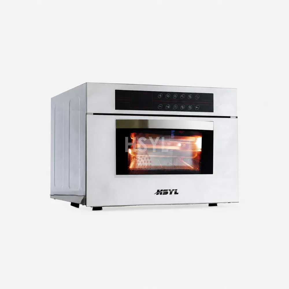
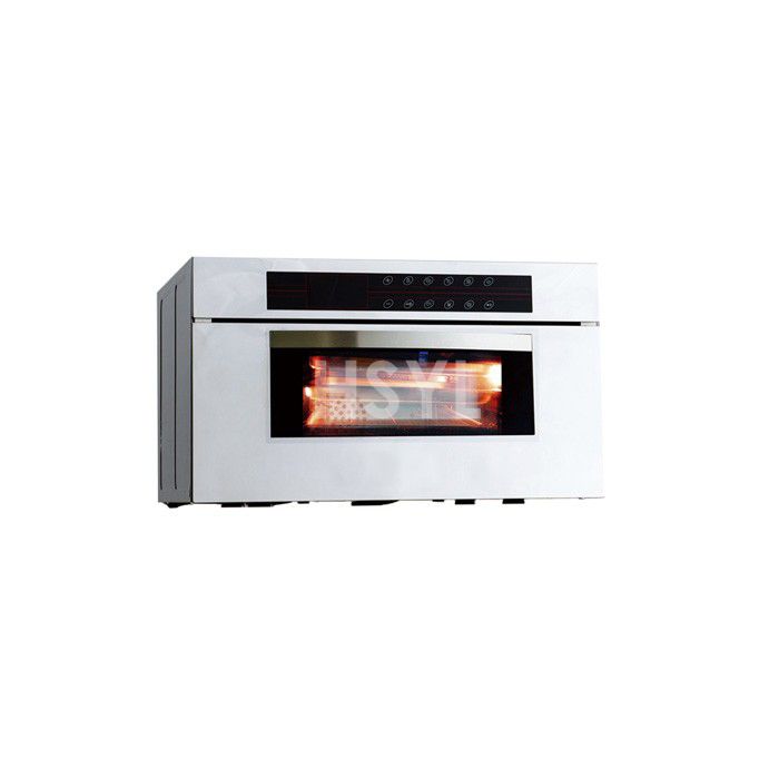
Direct Answer / Key Takeaway: Coordinate a combi oven installation using the exact model drawing, inlet water conditions, electrical supply and drain route before contractors complete rough-ins.
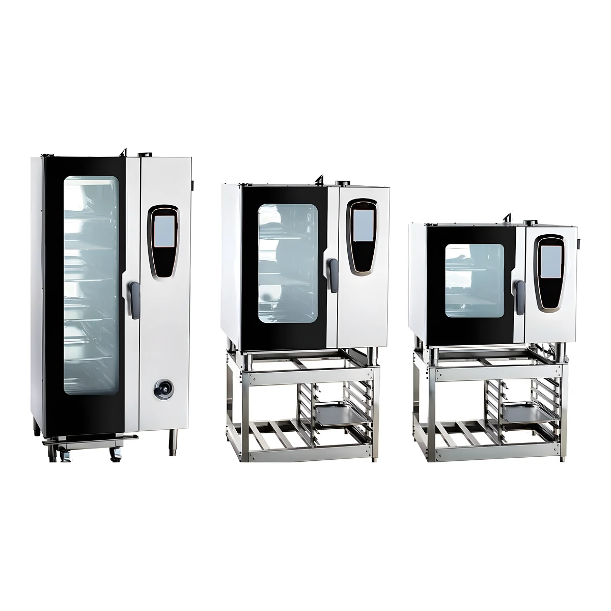
A combi oven can arrive with the correct pan capacity and still be impossible to commission because the building connections were set out from an old drawing. The installation interface schedule should identify the exact model and revision, then assign responsibility for every connection between the oven and the building.
Freeze the model before rough-in dimensions
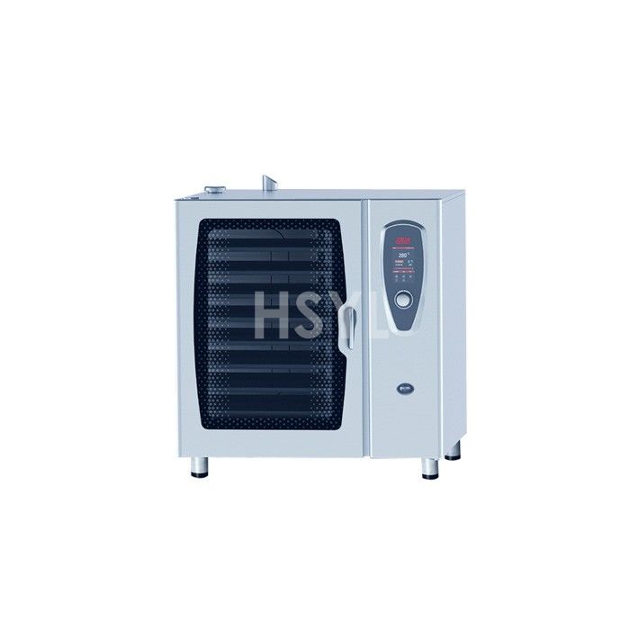
The catalog lists HCO6.1E and HCO6.2E with different GN formats, outside dimensions and electrical inputs. For the quoted versions, the table shows 19.0 kW and 22.0 kW respectively, both at 3N~380 V. These are model-specific catalog entries, not permission to size a circuit from this article. The delivered nameplate, installation instructions and site electrical design must agree.
Put the connection drawing beside the equipment schedule. Mark the oven's working position, door opening, service side and supporting stand or base. A connection that is technically nearby may become inaccessible behind a stacked appliance or prevent the unit being moved for service.
Record the water conditions the oven will receive
The same catalog table gives an R 3/4-inch inlet and a pressure range for the listed HCO models. A nominal pipe connection does not describe water quality or the pressure available while nearby equipment is drawing water. Obtain the current model's complete water requirements and measure the site conditions relevant to those requirements.
Combi oven water treatment selection belongs to that comparison. A filter or softener should not be copied from another appliance simply because it fits the inlet. Document the supply analysis, treatment arrangement, isolation point and replacement access. The contractor and supplier need a shared record of what reaches the oven after treatment.
Trace the discharge to its destination
Follow the proposed drain route from the oven outlet to the receiving drainage arrangement. Check the manufacturer's permitted connection method, temperature-related material requirements, available elevation and the site's approved provisions for separation and backflow protection. Do not draw an assumed drain fall through a cabinet that is already occupied by a stand or trolley guide.
Leave cleaning and inspection points accessible. If the receiving drain serves several appliances, the project team should assess their combined operation rather than reviewing the oven in isolation. This is a coordination task; a universal drain diameter or air-gap dimension cannot be specified without the model and local design.
Close the interface sheet with named responsibilities
| Interface | Information to agree | Acceptance evidence |
|---|---|---|
| Electrical | Delivered supply rating, connection arrangement and accessible isolation | Nameplate, current instructions and the responsible electrical professional's checks |
| Water | Required and measured inlet conditions, treatment and isolation | Model specification and recorded site results |
| Drainage | Outlet route, receiving connection and service access | Approved drawing and completed installation review |
| Space and ventilation | Door, service clearance, steam release and extraction arrangement where required | Model layout and project design acceptance |
Commissioning should compare the completed installation with this sheet before production is scheduled. Record departures and resolve them with the responsible contractor or supplier. A successful power-on alone does not establish that water treatment, drainage and service access have been coordinated.