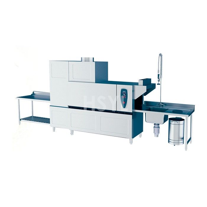
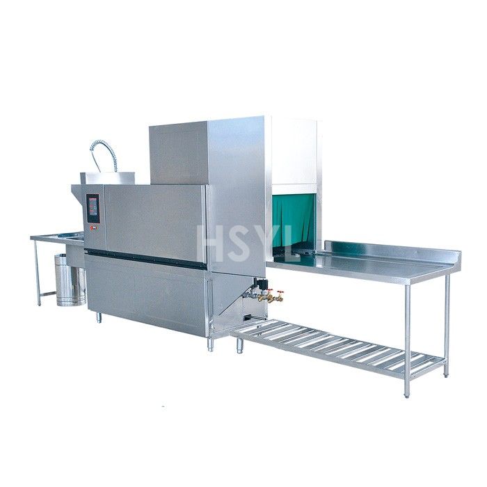
Direct Answer / Key Takeaway: Coordinate actual shipping sections, installed supports, field joints and discharge access before fixing floor troughs and utility routes for a flight line.
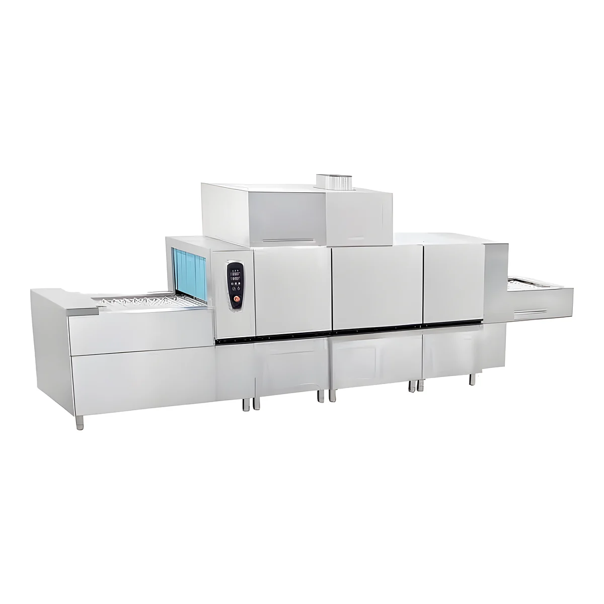
A long flight line needs an installed floor/interface plan, not a trough positioned from the outside dimensions alone. Confirm how the actual ordered machine is delivered, joined and supported before fixing permanent building work.
Obtain the supplier's shipping-section and final assembly drawings. Identify actual section weights, support positions, field joints and installation access requirements. Do not infer that a modular description permits the machine to be separated or lifted at any convenient point.
Overlay delivery and the finished installation

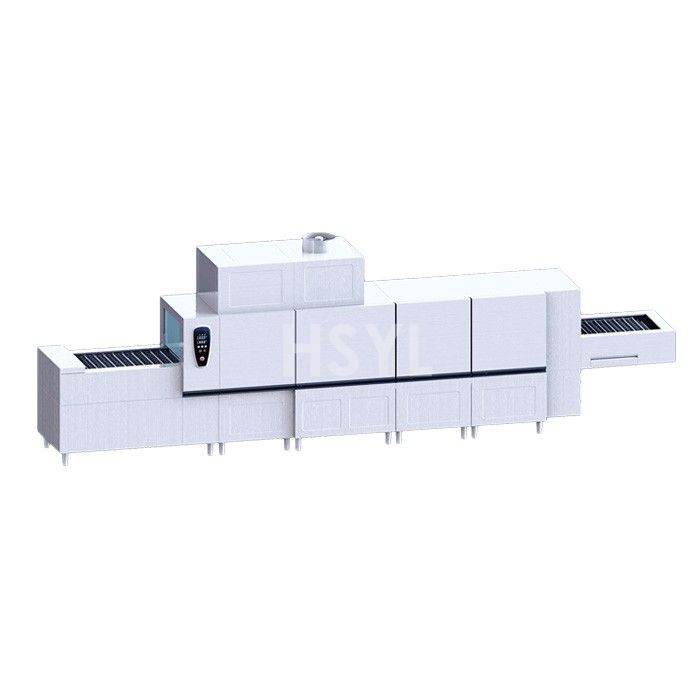
Have the competent handling team review the real route into the room, turning/access constraints and the manufacturer's permitted handling arrangement. Keep the space needed to join supplied sections visible before neighbouring equipment is fixed.
The competent building designer should check the actual installed support loads and floor arrangement. A floor trench, grate edge or slab opening may occupy a planned support or installation position. Resolve the supplied requirements and real construction rather than shifting a foot or bridge member in the field.
Use the interface-drawing review to coordinate the machine, surrounding tables and fabricated building-side elements before production or rough-in is approved.
Make service and discharge routes work together
Locate actual tank and accessory discharge connections, receiving drainage and required access on the assembled line. Have the competent plumbing designer resolve actual release conditions, materials and applicable protection/separation. A trough may collect permitted floor wash but is not automatically the approved destination for each machine connection.
Check how covers, grates and removable parts are handled with the machine in place. The route used to remove a strainer or service a connection should not rely on lifting an unsupported section or moving an unidentified utility.
Coordinate the real machine, booster and accessory electrical feeds with the assembled configuration. Cable and pipe routes must preserve the actual join, support and access requirements. Do not assign a high current or cable size from a general heater figure.
The approved commissioning plan should address field-joint completeness, real connections and required whole-line functional checks through competent roles. Do not treat one powered module as acceptance of the joined line.
Close support, joint and drain-access conflicts before the floor work becomes irreversible. The final drawing should show what is actually installed and who completes each interface, including the space required to assemble and maintain it.