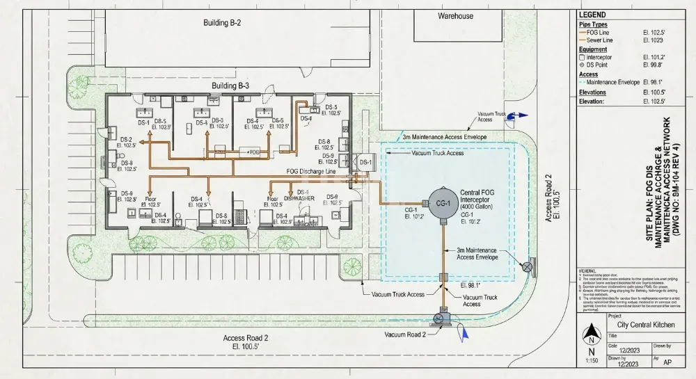
A dot labelled “drain” on an equipment plan is not a coordinated kitchen drainage design. The receiving trade still needs to know what leaves the equipment, when it flows, its temperature and solids/grease content, whether the connection is direct or indirect under local rules, where the receptor sits, and how both the line and grease-control device will be serviced.
Walk the kitchen and name every discharge
Number each source on the plan. Include equipment drains, relief or overflow paths, condensate, defrost water, sink and pre-rinse waste, floor cleaning, mop/service functions, ice or beverage waste where in scope and any intentional oil collection. Keep rainwater, sanitary fixtures and other building systems separate unless the project engineer explicitly coordinates them.
For every source, create one row in a discharge register:
| Register field | Decision it must support |
|---|---|
| Source and exact equipment | Stops a generic symbol from being reused for different waste streams |
| Discharge character | Water, condensate, solids, detergent, heat, grease or another defined load |
| Peak and event pattern | Continuous, batch dump, cleaning event or emergency/relief condition |
| Outlet | Size, elevation, direction, connection type and supplier limitation |
| Receptor and route | Location, elevation, air-gap/indirect arrangement where required, pipe route and cleanout |
| FOG decision | Whether and how local authority requirements apply |
| Owner | Who supplies, connects, tests, cleans and maintains each interface |
The equipment supplier should provide current outlet information for the exact model. The plumbing designer determines the building system. The local authority determines acceptable discharge and FOG controls. None of these roles should be replaced by an assumed connection copied from another project.
Coordinate the receptor in three dimensions
Plan and elevation must agree. A receptor can appear clear in plan while sitting above the equipment outlet, inside a wheel path, beneath an inaccessible panel or where a trolley cannot pass. Show finished floor level, falls, grating, receptor rim, equipment legs or plinth, outlet elevation, connection route and access for cleaning.
For mobile or roll-in equipment, test the full travel path and docking position. Hoses or tundishes must not become trip hazards or prevent cleaning. For fabricated items, coordinate cut-outs, upstands, sinks, troughs and drain positions before production. The UFGS 11 05 40 foodservice equipment specification is a U.S. federal guide specification; its detail-drawing requirements illustrate the value of showing equipment drain lines, floor drains and elevations. Project documents and local rules remain controlling.
Keep cooking oil out of the drainage assumption
Used cooking oil needs a defined collection, temporary storage and removal route. It should not be treated as an ordinary liquid discharge. The U.S. EPA notes that fats, oils and grease can clog public sewer pipes and pumps, and its FOG pretreatment resources describe local programme tools for food-service discharges. This is a reason to obtain the local wastewater authority’s criteria—not a substitute for them.
Map where oil is cooled or transferred according to the approved operating method, the container, spill control, route to pickup and responsibility. Check that staff do not carry hot oil across wet floors or customer routes. Grease interceptors or other devices must be selected and located from the applicable requirements and calculated duty, with access for inspection, pumping and cleaning.
Design floor cleaning as a controlled event
Sketch the cleaning sequence: where debris is removed, where water is applied, how it is contained, which drains receive it and what equipment must move. A floor drain cannot compensate for poor falls, inaccessible edges or uncontrolled spray. Confirm chemical compatibility and whether washdown is appropriate around the exact appliances and electrical components.
Ask what happens during a blockage or large batch discharge. Identify overflow paths and nearby sensitive areas. Avoid routing a failure toward dry stores, electrical panels, cold-room thresholds or occupied public space.
Close the interfaces before construction
Hold a coordinated review using the discharge register, equipment cut sheets, plan, elevations and builder’s work openings. Resolve receptor coordinates, pipe routes and levels, grease-control decision, cleanouts, access panels, fire stopping, waterproofing, testing and trade ownership. Record unresolved items as holds.
Release the drainage package with the wider utility record
The live commercial kitchen utility schedule guide provides the wider service register. For made-to-measure sinks, benches or troughs, coordinate the interfaces with the custom stainless-steel equipment category. A final drain position should be released only when equipment and building drawings agree.